

[:es]
SERVICIO DE INSPECCIÓN MFL EN SENTIDO INVERSO EN FLOWLINE DE GAS CON MUY BAJO FLUJO
PRESENTACIÓN DEL CASO:
Una de las operadoras más grandes de Bolivia, que opera campos en el Sur del país, ha encontrado un nuevo desafío durante los últimos años: la reducción de producción gasífera y el incremento de la presencia de agua en la producción de algunos de sus mega pozos.
La mayor presencia de agua incrementa la posibilidad de encontrar fenómenos de corrosión en las líneas de acero de transmisión de producción o “flowlines”, que van desde la planchada de los pozos hacia la planta de tratamiento.
Debido a la presencia de grandes cantidades de agua, se torna imprescindible poder realizar inspecciones instrumentadas en línea (In Line Inspection), siendo estas utilizadas normalmente cada 5 años para verificar la integridad de la línea y poder identificar las anomalías para mantener una operación segura en el tiempo.
Sin embargo, debido a la disminución de la producción y por consiguiente la reducción de sus caudales por debajo de los mínimos requeridos, estas líneas se han visto afectadas para poder conducir inspecciones de forma convencional.
Una inspección MFL y los estudios Fitness For Service que provee Morken Group son ideales para verificar el estado de las líneas. La situación problemática es: ¿Cómo correr herramientas MFL convencionales en líneas con flujo extremadamente bajo?
El cliente planteó el reto de realizar una campaña de 7 inspecciones back to back, a flowlines de 10”, en 2 campos distintos con configuraciones distintas de herramientas donde 3 de las inspecciones se deberían realizar considerando un flujo muy bajo.
-
Fecha de intervención: Junio 2022
-
Activo: Servicio de inspección mfl en sentido inverso en flowline de gas con muy bajo flujo
-
Localización: Bolivia
SOLUCIÓN
Tomando el antecedente exitoso de inspecciones instrumentadas previas realizadas en configuración reversa en flowlines de 10” y 12” en años recientes, se trabajó con el cliente para llevar a cabo las inspecciones de líneas de bajo flujo acorde a dicha configuración.
Junto con el cliente se optó por la siguiente configuración:
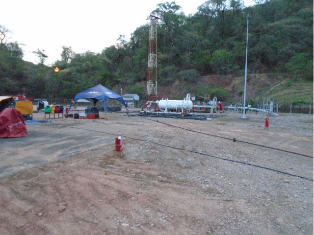
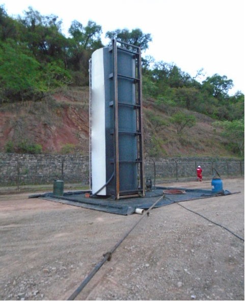
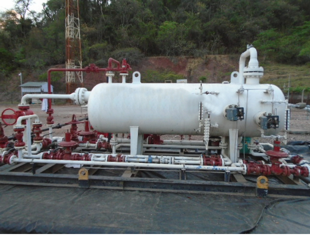
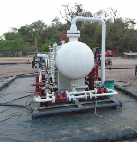
El gas viajará en sentido inverso a su flujo natural, es decir, en lugar de que el gas viaje desde la planchada del pozo hasta la planta para ser tratado, se inyectará gas tratado proveniente de otros pozos a la línea, desde el punto final de la línea en la planta, para llevar el gas hasta facilidades temporales en la planchada con separadores conectados al flare que realizará la quema controlada del gas utilizado para impulsar el pig.
Para acondicionar la línea se necesitó colocar un “spool” en la planta que conecte una línea con gas de salida de la planta (gas tratado) con el flowline en su trampa de recepción en la misma planta. Además de contratar el separador para colocar en la planchada del pozo, se ocupó el flare del mismo pozo.
Esta tarea se realizó en dos bloques petroleros distintos de la misma operadora.
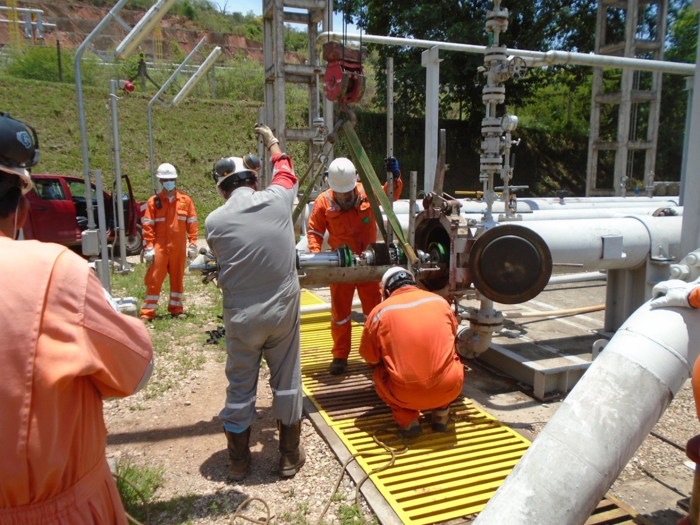
Con el pozo a inspeccionar cerrado se procedió a utilizar la trampa naturalmente utilizada como receptora en planta en calidad de lanzadora hacia pozo, donde la trampa lanzadora hizo las veces de trampa receptora.
El gas de la línea era llevado a un flare donde era quemado, siendo esta la mayor ventaja en lugar de utilizar agua, la cual es mucho más difícil para tratar y realizar su disposición final.
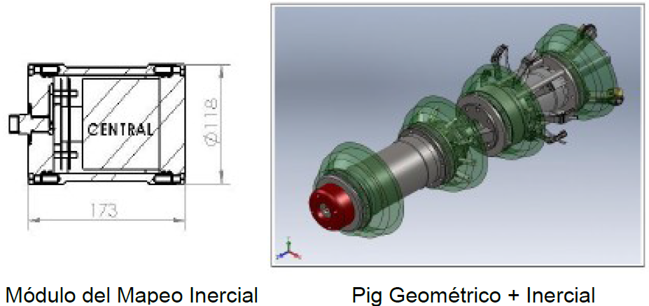
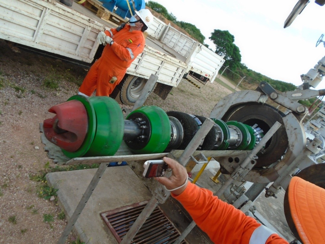
La Gerencia de Mantenimiento y el departamento de integridad del cliente evaluaron alternativas y trabajando con Morken Group se seleccionó una herramienta de inspección instrumentada MFL y una GEO con Unidad de Mapeo Inercial (IMU).
Con la adición del Módulo Inercial, la tubería es georreferenciada y las coordenadas XYZ son suministradas a los eventos como: anomalías, soldaduras, válvulas y otros reportados en los informes finales de la inspección con GEO + MFL, lo que auxilia en la ubicación y la correlación de las anomalías en campo.
A partir de los datos inerciales y con futuras inspecciones que apliquen la misma técnica será posible la realización de estudios comparativos de la traza y flexión de la tubería, lo que permite identificar movimientos del ducto.
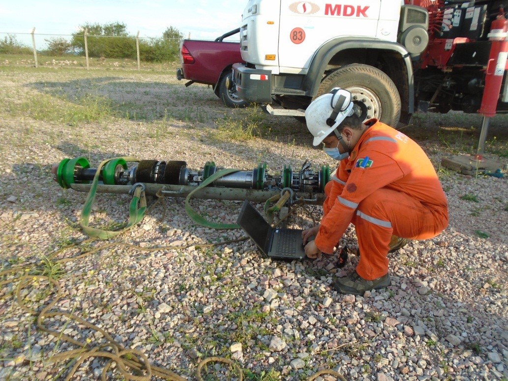
El módulo inercial registra movimientos lineares y angulares del Pig por medio de sus 3 acelerómetros y 3 giroscopios. El dato registrado es procesado por sofisticados algoritmos que en conjunto con las informaciones de los odómetros y de los marcadores magnéticos georreferenciados mantienen la precisión especificada.
RESULTADOS Y BENEFICIOS:
La campaña de inspección se completó exitosamente, y todas las corridas realizadas inclusive en las líneas que fueron corridas en sentido inverso fueron validadas para su análisis y posterior reporte; Morken Group le entregó al cliente los informes sobre las limpiezas y pasaje de placas calibradas corridas, corridas geométricas o caliper y corridas MFL.
Los datos recopilados fueron suficientes para elaborar los informes Fitness For Service, brindando al cliente opciones para planes de reparación, intervalo recomendado de reinspección, y confirmación de aceptación de las características de pérdida de metal para poder trabajar a la MAOP.
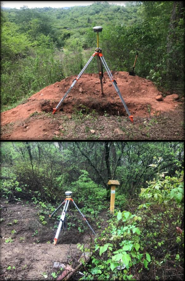
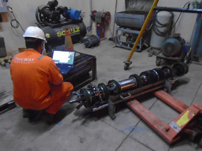
De acuerdo a la información recolectada por el módulo inercial IMU incorporado al PIG Geométrico se pudo informar la localización de todas las anomalías identificadas. Para ello se utilizaron los registros reportados por el módulo inercial y la georreferenciación realizada en terreno para poder ubicar cada anomalía informada mediante hojas de excavación con los detalles de la información de la inspección MFL.
MFL INSPECTION SERVICE IN REVERSE DIRECTION IN GAS FLOWLINE WITH VERY LOW FLOW
PRESENTATION OF THE CASE:
One of the largest operators in Bolivia, which operates fields in the south of the country, has encountered a new challenge in recent years: the reduction of gas production and the increase in the presence of water in the production of some of its mega wells.
The greater presence of water increases the possibility of finding corrosion phenomena in the production transmission steel lines or “flowlines”, which go from the well plate to the treatment plant.
Due to the presence of large amounts of water, it is essential to be able to carry out instrumented online inspections (In Line Inspection), these being used normally every 5 years to verify the integrity of the line and to be able to identify anomalies to maintain a safe operation in time.
However, due to the decrease in production and consequently the reduction of their flows below the minimum required, these lines have been affected to be able to conduct alteration in a conventional way.
An MFL inspection and Fitness For Service studies provided by the Morken Group are ideal for verifying the condition of the lines. The problem situation is: How to run conventional MFL tools in extremely low flow lines?
The client posed the challenge of carrying out a campaign of 7 back to back inspections, at 10” flowlines, in 2 different fields with different tool configurations where 3 of the inspections were carried out considering a very low flow.
-
Fecha de intervención: June 2022
-
Activo: MFL inspection service in reverse direction in gas flowline with very low flow
-
Localización: Bolivia
SOLUTION
Building on the successful track record of previous instrumented inspection performed in reverse configuration on 10” and 12” flowlines in recent years, we worked with the client to carry out the inspection of low-flow lines according to said configuration.
Together with the client, the following configuration was chosen:
The gas will travel in the opposite direction to its natural flow, that is, instead of the gas traveling from the well pad to the plant to be treated, treated gas from other wells will be injected into the line, from the end point of the line in the plant, to take the gas to the temporary facilities in the ironing with separators connected to the flare that will carry out the controlled burning of the gas used to drive the pig.
To condition the line, it was necessary to place a “spool” in the plant that connects a line with gas coming out of the plant (treated gas) with the flowline in its reception trap in the same plant. In addition to contracting the separator to place on the well plate, the flare of the same well was taken care of.
This task was carried out in two different oil blocks of the same operator.
With the well to be inspected closed, the trap naturally used as a receiver in the plant was used as a launcher towards the well, where the launcher trap served as a receiving trap.
The gas from the line was taken to a flare where it was burned, this being the greatest advantage instead of using water, which is much more difficult to treat and carry out its final disposal.
The Maintenance Management and the customer integrity department evaluated alternatives and working with Morken Group selected an instrumented inspection tool MFL and a GEO with Inertial Mapping Unit (IMU).
With the addition of the Inertial Module, the pipeline is georeferenced and the XYZ coordinates are supplied to the events such as: anomalies, welds, valves and others reported in the final reports of the inspection with GEO + MFL, which helps in the location and consequences of anomalies in the field.
From the inertial data and with future tests that apply the same technique, it will be possible to carry out comparative studies of the trace and bending of the pipe, which allows identifying movements of the pipeline.
The inertial module records linear and angular movements of the Pig through its 3 accelerometers and 3 gyroscopes. The recorded data is processed by sophisticated algorithms that, together with the information from the odometers and the georeferenced magnetics, maintain the specified precision.
RESULTS AND BENEFITS:
The inspection campaign was successfully completed, and all the runs carried out, including the lines that were run in the reverse direction, were validated for analysis and subsequent reporting; Morken Group delivered to the client the reports on the cleaning and passage of calibrated plates, geometric or caliper runs and MFL runs.
The data collected was necessary to produce the Fitness For Service reports, providing the customer with options for repair plans, recommended re-inspection interval, and confirmation of acceptance of metal loss characteristics in order to work with the MAOP.
According to the information collected by the IMU inertial module incorporated into the Geometric PIG, the location of all the identified anomalies could be reported. For this, the records informed by the inertial module and the georeferencing carried out on the ground were used to be able to locate each anomaly reported through excavation sheets with the details of the information from the MFL inspection.
